AVRminiV4.0 Quick-Start Guide
Written by Pascal Stang | Updated:
Sunday February 20, 2011
AVRmini V4.0 Board Overview:
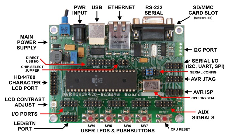
Connections and Interfaces:
- AVR Processor
- In the center of the board is a 40-pin socket which can accept dozens
of different AVR processors. Popular ones include the ATmega16, ATmega32,
and ATmega644.
- Advanced Interfaces
- USB
- The AVRmini's USB interface is based on a FT232R chip from FTDI
(www.ftdichip.com). This chip's
primary function is to act as a USB->Serial converter, allowing
the user to get serial data and debug information from the board without
requiring a standard RS-232 serial port. The USB interface can also
be used to reprogram the code in the AVR processor using a special
utility, ftisp. No USB programming knowledge
is necessary to use the USB port.
- Ethernet
- The AVRmini's Ethernet interface is an ENC28J60 Ethernet MAC/PHY
chip from Microchip Technologies (www.microchip.com).
The chip provides 10Base-T Ethernet on one side, while connecting
to the AVR processor via a serial SPI interface. The Ethernet interface
can send and receive any kind of traffic including raw ethernet packets,
TCP/UDP/IP, Appletalk, NetBIOS, etc. Drivers and some IP networking
support for AVR is provided in AVRlib.
- SD/MMC Flash Card Slot
- The AVRmini has a standard SD/MMC flash card slot on the underside
of the board, below the RS-232 serial connector. A memory card installed
in this slot can give the AVR processor access to gigabytes of storage.
The AVR processor talks to the card via a serial SPI interface.
- Basic Interfaces
- RS-232 Serial Port
- This is a standard RS232-compliant serial port which can be used
to communicate with a computer or any other serial device. Use a straight-thru
9-pin serial cable (not null modem) to connect the board to a host
PC.
- I/O PORT Headers
- The I/O port headers bring out all of the AVR processor's I/O pins
for general use. The I/O port pinout is that same as used on the STK500.
- LED/BTN Port
- The LED/BTN port connects to the user LED and pushbutton array.
For simple input and output, you can connect LED/BTN to one of the
AVR I/O ports using a regular 10-pin ribbon cable. The LEDs are driven
by port bits 0-3, and switches read by bits 4-7.
- HD44780 Character LCD Port
- This 14-pin port can interface directly with common and inexpensive
character LCD modules (which have a matching 14-pin connector). Some
LCDs may have two extra pins to carry power for a backlight.
- I2C PORT
- This port provides easy access to the AVR processor's 2-wire I2C
bus and also provides power and ground connections.
- AVR ISP / AVR JTAG
- These two ports allow external programmer and debugger tools to
be connected to the AVRmini. For example, an Atmel STK500 board can
be used to reprogram the AVR processor via the ISP connector. Similarly,
an Atmel JTAG-ICE debugger can be connected to the JTAG port to allow
in-circuit debugging.
- NOTE: The AVRmini board offers several ways to (re)program
the AVR processor without any additional hardware
(see ftisp and bootloaders).
- Power
- The board can be powered either through USB, or via a standard round
DC jack.
The power source with the higher voltage is automatically selected.
- DC Jack
- Power into the DC jack should be limited to less than 18V, and must
be at least 6.5V to get a full 5V regulated output.
- The input voltage may be any polarity if using an isolated power
supply, like a typical wall adapter, to power the board.
- USB
- In the absense of a "main" power source, the board can
power itself from USB.
- When powered from USB, you may notice that the board's power drops
to about 4.5V. This is normal and the board will continue to function.
- Avoid drawing more than 250mA/500mA when powered via USB from a
laptop/desktop respectively.
Jumpers and Configurations:
- Jumpers
- SER CONFIG jumpers
- Jumpers on the SER CONFIG header route signals having to do with
the board's serial ports.
- Use USB serial: Jumper pins 1&3 and 2&4.
This will connect the AVR processor to the USB serial (COM) port.
- Use RS-232 serial: Jumper pins 3&5 and 4&6.
This will connect the AVR processor to the RS-232 serial port (DB-9).
- CSJMP jumpers (chip select jumpers)
- Enable SD/MMC Card: Jumper pins 1&2 to connect
the flash card chip select to PB0. This enables the flash card interface.
- Enable Ethernet: Jumper pins 3&4 to connect
the ethernet chip select to PB1. This enables access to the ethernet
controller chip.
- Enable Ethernet IRQ: Jumper pins 5&6 to connect
the ethernet interrupt (IRQ) to PB2.
- USB I/O jumpers
- Pins 15 and 16 on the USB I/O header serve special functions. They
enable AVR processor reprogramming via USB.
- USB-to-ISP: Jumper pins 13 & 15 to enable ISP
reprogramming via USB. This is required for the ftisp
tool to work.
- USB-to-JTAG: Jumper pins 14 & 16 to enable
JTAG reprogramming via USB. Software support for this is still in
development.
Installing software tools:
- First, you'll need a set of tools to compile and load programs. Download
and install the following tools:
- AVR-GCC compiler - this is an excellent free C/C++
compiler for AVR processors
- For Windows/PC machines, the WinAVR
package
- For Linux/PC machines, you can install AVR-GCC directly via your
package manager or update manager
- For Mac OSX, there are solid versions of AVR-GCC for OSX, but I
have not used them myself.
- Procyon AVRlib - this is a suite of code libraries
for the AVR and will make your life much easier. Get it [here].
- ft-isp USB Programmer Utility - (get
it [here])
Allows direct ISP programming of AVR processor via USB connection. No
bootloader needed.
Run ftisp from the command line with no arguments and
it will list options and usage examples.
ftisp requires the following in order to work
- AVRminiV4.0 board must be connected to PC via USB.
- FTDI V2.xx.xx (CDM) drivers must be installed (Get drivers here:
www.ftidchip.com).
- Pins 13&15 of USB I/O header must be connected with a shorting
block.
- Next, test your tools:
- Open a command prompt (in windows, START->RUN->'cmd')
- From the prompt, run >make
You should get a report of "make: *** No targets
specified...". If you didn't see this, either AVR-GCC did
not install properly, or you have a problem with your path (google: "windows
environment path").
- Take the ftisp.exe you downloaded and copy it to the
folder: .../winavr/bin (this is the location where you
installed WinAVR)
- Now run >ftisp at the command prompt. You should
see the ftisp usage and examples printed.
Compiling a simple AVR program:
- It's easiest to begin with a program that already compiles, and then modify
it.
- First prepare a folder where you would like to keep the code that you
write, for example:
c:\code
- Download the following example: helloworld.zip
- Unzip it into your code folder so that you have:
c:\code\helloworld\helloworld.c
c:\code\helloworld\global.h
c:\code\helloworld\makefile
- Open a command prompt, and change to the helloworld
folder:
>cd c:\code\helloworld
- Run make
c:\code\helloworld>make
- Make will proceed to build the helloworld
application and should end with "Errors: none".
- Congratulations, you've compiled an AVR application. Keep the command
prompt open for the next steps.
- Now that we know how to build helloworld, we need to modify
the application so that it actual works on our processor and our board. These
steps are common anytime you start a new code project or change hardware.
- First we must compile for the correct AVR processor
- Open makefile in your preferred code or text editor
(notepad is fine)
- Locate the 'MCU =' line and edit it to match the
processor you have in your board
If your processor is an atmega644 also modify the 'AVRLIB_SRC
=' line, and replace timer.c with timerx8.c
- Save makefile.
- Next we must tell the program what CPU speed we are using:
(This is important to make timing and baud rates within the program accurate)
- Open global.h in your preferred editor
- Modify the F_CPU define to match the actual clock
frequency of your processor. Use units of Hz.
The CPU frequency is usually determined by the crystal installed in
the AVRmini board.
- Save global.h.
- Finally, we look at helloworld.c to see what the program
will do
- Open helloworld.c in your preferred editor
- Read the program comments. The program uses several elements from
AVRlib to simplify basic serial I/O
- Modify the uartSetBaudRate(9600); to use 115200 baud
instead of 9600 baud.
- Save helloworld.c.
- Now we build the application again by running make at
the command prompt:
c:\code\helloworld>make
- Hopefully, the program should build without error. You should have lots
of files in your folder now, including helloworld.hex and
helloworld.bin.
- Next we load the compiled executable into the AVR processor. Keep the
command prompt open.
Loading code into the AVR processor on the AVRminiV4.0:
NOTE: For now, this guide only covers using the 'ftisp'
utility to load code, although many other methods are possible.
- First make sure there is jumper between pins 13&15 of the USB I/O header
on your AVRmini board.
- Connect your AVRmini to your PC via USB cable.
- When Windows asks for a driver, be sure to direct it to the FTDI CDM driver
you downloaded from the Install section above.
The default FTDI windows driver will not work!
- Now run the following ftisp commands to erase and reprogram your processor:
For 'ftisp' version 1.x:
c:\code\helloworld>ftisp -e

    c:\code\helloworld>ftisp -wf helloworld.bin
For 'ftisp' version 2.x:
c:\code\helloworld>ftisp -E -fw helloworld.bin
- The processes should take about 10 seconds. If errors are reported, read
them carefully to see what went wrong.
Monitoring the serial output:
- If the above programming steps worked, then your processor is already executing
your code.
- To see the serial output, do the following:
- Check the SER CONFIG header of your AVRmini and make
sure it's properly configured to use either the USB or RS-232 ports for
serial output. For full info on the SER CONFIG header,
see the hardware reference above.
- Open a serial terminal program, such as HyperTerminal or TeraTerm. Several
are available for free on the internet.
(Note: HyperTerminal has numerous bugs, but it's included with Windows under
Start->Programs->Accessories->Communication)
- In the terminal program, open the COM port that is connected to the AVRmini
(either USB-based or RS-232)
- Set the communication speed for 115200 baud.
- Press RESET on your AVRmini board to restart your AVR program.
- You should see "Hello World!" printed on the screen, as sent
by the AVR processor.
- Now modify the helloworld.c program to make it your own.
- Edit helloworld.c and change the printed message, or
something else.
- Rebuild the code by issuing the make command.
- Use ftisp to erase and reprogram your processor with
the new code.
NOTE: If using USB for your serial communications, you must tell your
terminal program to disconnect before using ftisp, then reconnect afterward.
- Press RESET.
- You should see your new message printed in the terminal program.
Advanced Code Examples:
Written by Pascal Stang | Updated:
Sunday February 20, 2011