These commands can be entered interactively or by script via the
controller serial port. To communicate interactively with the controller, use
a standard serial terminal program such as HyperTerminal or TeraTerm under windows,
or minicom under Linux.
All commands are a single command letter with up to two integer numeric arguments
seperated by spaces. Commands are case-sensitive (ie. 'G' is not the same
as 'g'). Here is an example command session showing the meaning of each command
and various syntax:
AVR Motor Controller Commands |
Notes |
General Commands |
|
Description |
Cmd |
Arg0 |
Arg1 |
|
| Help |
'?' |
. |
. |
Displays on-line help for available commands |
| Select Motor |
's' |
motor# |
. |
Select motor to control (1 or 2) |
| Motor Control Mode |
'm' |
mode |
. |
mode=0: Control off (motors disabled)
mode=1: Position control
mode=2: Velocity control (use 'v' command to set velocity)
mode=3: Cross-linked control |
| Goto Position (PID) |
'g' |
position [tics] |
. |
Drives selected motor to requested position under direct PID control. |
| Goto Position (PID) |
'G' |
pos1 [tics] |
pos2 [tics] |
Drives both motors simulanteously to requested positions under direct
PID control (NOTE: pos1 need not equal pos2). |
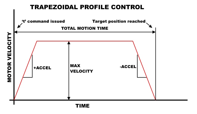
| Goto Position (Prof) |
't' |
position [tics] |
. |
Drives selected motor to requested position under PID+PROFILE control.
Uses trapezoidal motion profile. |
| Goto Position (Prof) |
'T' |
pos1 [tics] |
pos2 [tics] |
Drives both motors simulanteously to requested positions under PID+PROFILE
control. Uses trapezoidal motion profile. |
| Reset Encoders |
'z' |
pos1 [tics] |
pos2 [tics] |
Resets the encoder counters. Allows reassigning the current physical
position to user-selected encoder values. If no arguments are specified
then encoders reset to zero. |
| Read Motor Current |
'c' |
. |
. |
Returns motor current in mA (if current sensing is connected) |
Configuration Print/Read/Write |
|
| Config Print |
'L' |
. |
. |
Prints settings and coefficients that are currently active. |
| Config Write |
'w' |
. |
. |
Stores all current settings and coefficients into EEPROM. The settings
are automatically loaded at power-on. |
| Config Load |
'l' |
. |
. |
Load settings and coefficients from EEPROM. Restores all settings to
those last saved with 'w' command. |
PID Tuning Assistance |
|
| Record Response |
'r' |
. |
. |
Sets currently selected motor for response recording. Response recording
records the actual motor trajectory for the first 200points after the
next 'g' command. |
| Upload Response |
'R' |
. |
. |
Returns the recorded motor trajectory data from 'r' command. Each data
point is the motor position (encoder value) as it approached the target
position requested by the 'g' command. |
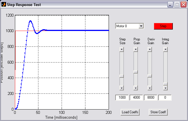
| Step Response Test |
'f' |
. |
. |
Runs automatic motor step-response test. |
Trapezoidal-Profile Controller Settings |
|
| Set Max Velocity |
'v' |
vel |
. |
Sets the maximum velocity to be used under trapezoidal profile control.
Also used in velocity control mode to set desired velocity. |
| Set Max Acceleration |
'a' |
accel |
. |
Sets the acceleration to be used under trapezoidal profile control |
PID Controller Settings |
|
| Set Prop. Gain |
'P' |
Kp |
. |
Sets the Proportional gain for currently selected motor [units TBD] |
| Set Integral Gain |
'I' |
Ki |
. |
Sets the Integral gain for currently selected motor [units TBD] |
| Set Derivative Gain |
'D' |
Kd |
. |
Sets the Derivative gain for currently selected motor [units TBD] |
| Set Windup Max |
'W' |
wm |
. |
Sets the maximum value for integral error (clamping value) |
| Set Output Max |
'M' |
om |
. |
Sets the maximum motor drive level [PWM units, out of 1200] |
| Set Deadzone |
'Z' |
dz |
. |
Sets the minimum motor drive level [PWM units, out of 1200]
Below this level, the motor power will be clamped to zero. |
System Test Commands |
|
| Encoder Test |
'e' |
. |
. |
Prints encoder count value for both motors. Press any key to exit. |
| Motor Driver Test |
'q' |
. |
. |
Runs motors in ramp test pattern in both directions. Press RESET to
exit. |
| This command list current
as of firmware V1.6g, but is subject to change. |