|
The Serial-to-UDP adapter (or just Serial-UDP) translates serial port data into UDP/IP network packets and sends them over any standard ethernet network. It also receives UDP/IP packets from the net and routes the data through the serial port. In essence, the board allows an ordinary serial device to communicate via ethernet. Two boards together can create a virtual serial link where all the data passes over an ethernet network, instead of the usual serial cable.
Serial-UDP uses standard UDP/IP packets to pass all data and control signals. Therefore, the adapter can be used with almost all standard networking equipment including routers, bridges, switches, wireless LAN devices, etc.
Common uses of Serial-UDP include:
The Serial-UDP adapter uses the following ports:
Port |
Description |
4950/UDP |
Control commands are sent over this port |
4951/UDP |
Serial data is sent over this port |
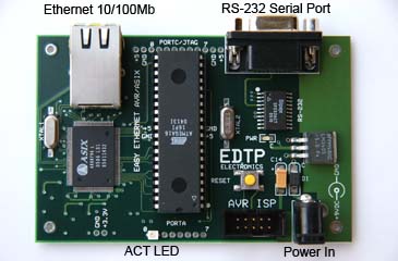
Serial-UDP is built from a modified EasyEthernet/AVR board from EDTP Electronics. It uses an Atmel AVR ATmega16 processor to handle the ethernet interface, network protocols, and serial I/O.
Interface/Indicator |
Description and Specs |
Power In |
Accepts 7-12VDC @ 150mA to power the Serial-UDP board. Using 9VDC is preferred to keep regulator from getting hot. |
RS-232 Serial Port |
RS-232 DB9 Female Connector (DTE wiring) |
Ethernet |
Autonegotiating 10/100BaseT Ethernet |
| ACT LED |
|
| AVR-ISP Connector |
AVR In-System Programming port (used for firmware upgrades) |
There are several configurable network and serial port settings in the Serial-UDP adapter. Follow this procedure to get to the configuration menu:
Configuration |
Description |
IP Address |
This is the IP address assigned to the Serial-UDP adapter. It must be a valid IP address for the network on which the adapter operates. For private/isolated networks, use IP addresses in the range 192.168.x.x. |
Netmask |
The netmask for the network on which the adapter operates. Often this is 255.255.255.0. |
Gateway IP Address |
The IP address of the router or gateway on the local network. |
Dest IP Address |
The IP address where serial data should be sent. This may be another Serial-UDP adapter that forms a complete serial-to-ethernet-to-serial bridge, or a computer that will process the serial data itself. |
Serial Baud Rate |
The baud rate used for general operation. Note: Boot-up messages are always sent at 115200bps. |
Serial Packet Size-Out |
If this many characters are received over the serial port, they are immediately sent over the network. This will override the timeout. |
Serial Packet Time-Out |
If this amount of time goes by with no new characters received over the serial port, then the data already received is sent over the network. |
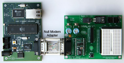
Since Parallax BasicStamps are programmed via a serial port, you can use a pair of Serial-UDP adapters to program a Stamp remotely over the network. To do this, follow this procedure: